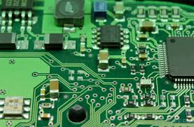
A PCB file viewer is a fundamental tool for every engineer and designer in the electronics industry. It provides the capacity for PCB designs to be tested and certified before production begins. A proper usage of the PCB file viewerto find possible errors before manufacture can save you time and money in the entire effort. But this tool can extremely impact your efforts if you know how to make the most of it.
Get Familiar With The Viewer
Get to know the potential of the viewers An appropriate PCB file viewer tool will also be able to offer 2D as well as 3D views of the board, enabling a thorough analysis of the layout from various dimensions. Getting a better knowledge of the software abilities, like layer view mode, part highlighting, or very detailed measurement tools can increase your efficiency and your capability of spotting issues that may be not visible in just a certain view mode.
Check for Component Clearance
Put the file in the viewer - check that it does not collide with any other board components. There must be enough room between different components to avoid short circuits and to ensure that components can release heat. The vast majority of viewers will provide you with tools to measure distances between components and those are no larger than a couple of millimeters, making sure that the layout retains the proper requirements that the physical world imposes.
Check for Trace Widths and Spacing
Another way that a PCB file viewer can be used is - to ensure trace widths and spacings meet the required electrical requirements Trace width must be able to handle the anticipated current, and spacings must be enough to avoid crosstalk, etc it needs to be. For standard PCB designs, you typically need trace width of 0.1mm for low current signals, and wider for higher currents, with appropriate spacings.

Use the Layer Inspection Feature
Each layer will be inspected individually A good PCB file viewer can view the board as you can switch between multiple layers of the board. I would say the main use for this check is that regarding internal layers, that are invisible if you have a physical model. By examining them layer by layer..., you do not only know that you placed the vias in the correct location, but you also know that there are not sudden stops or shorts in between the internal routes.
Analyze for Signal Integrity
Analyze signal integrity on the viewer using simulation tools More-advanced viewers can simulate signal behavior on the circuit, which can help identify potential issues (signal reflection, timing problems) before the board hits the manufactured stage. This can be crucial for high-speed designs in which signal degradation can result in device errors.
Inspect Against Manufacturer SpecRequirements
At last, check whether your design fits the manufacturer parameters throughthe PCB file viewer as well. This will involving checking file formats, layers, and any manufacturer-specific requirements that could affect the way the board will be manufactured. Most PCB file viewers provide validation checks that link your design directly to manufacturer rulesets, meaning there is less of a chance that your board will run into problems on the production line.
Using a PCB file viewer correctly isn't just about opening your design and taking a look, it's an interactive process where you need to work through the capabilities of the viewing tool to offer a complete test of your PCB design. This proactive review process helps to reduce risks, improve design quality, and facilitate an easier transition from design to production.